- Demonstrate what I have I learned through creating simple breadboard
- Explain each component of the circuit
- Make a power point presentation highlighting the components of the circuit
- Reference online sources used
- Compare progress to proposed gantt chart and make changes reflecting the complexities of the circuit and the learning curve I went through in understanding simple circuits
-show the previous circuit and explain the components and what they mean
-show the goal of the circuit
Monday, November 26, 2018
Tuesday, November 20, 2018
From Schematic to Breadboard
Connecting a battery to the circuit board; connect the red wire to to the red (positive) side of the power rail, and the black wire to the blue (negative) side of the power rail. You can put the red and black wires across both power rails, having power across the breadboard.
Rows are conductive and interconnected; if you plug in a wire to one of the five holes the entire row is connected. In order to connect each side need a jumper wire.
Jumper is wire is more versatile than a jumper cable.
Schematics can be read vertically, horizontally, or through a battery schematic (parallel vs. series).
Place the LED vertically. Connect a wire to the cathode of the LED and the negative (blue) side of the power supply.
Jump the gap with a resistor.
https://www.youtube.com/watch?v=5ZBPqKkCgIk 14:32 min
Monday, November 19, 2018
Connections on breadboard
When putting parts on a breadboard their connections on the breadboard are more important than their positions on the circuit diagram. It is recommended to put the IC in the middle of the board and adding on more components around it. Not all components have suitable leads and so suitable ones need to be soldered using single-core plastic wire of 0.6mm diameter.
https://electronicsclub.info/breadboard.htm
https://electronicsclub.info/breadboard.htm
Friday, November 16, 2018
Wiring/ Going from design to connections
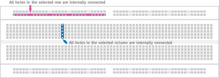
All of the holes in a selected row or column are internally connected. Connected holes are called nodes. In order to interconnect rows and columns (nodes) a cable is needed going from a hole in the column to a hole in a row. The five holes in the column are electrically connected.
https://www.sciencebuddies.org/science-fair-projects/references/how-to-use-a-breadboard
A positive bus (power rail) can be identified through power, plus sign, and red color.
A negative bus (power rail) can be identified through ground, negative sign, and blue or black color.
Breadboard Diagram: Different from schematic and circuit diagram which use symbols to represent electrical components; breadboard diagrams show components to how they actually look like.
Thursday, November 15, 2018
How to use a bread board?
https://learn.sparkfun.com/tutorials/how-to-use-a-breadboard/all
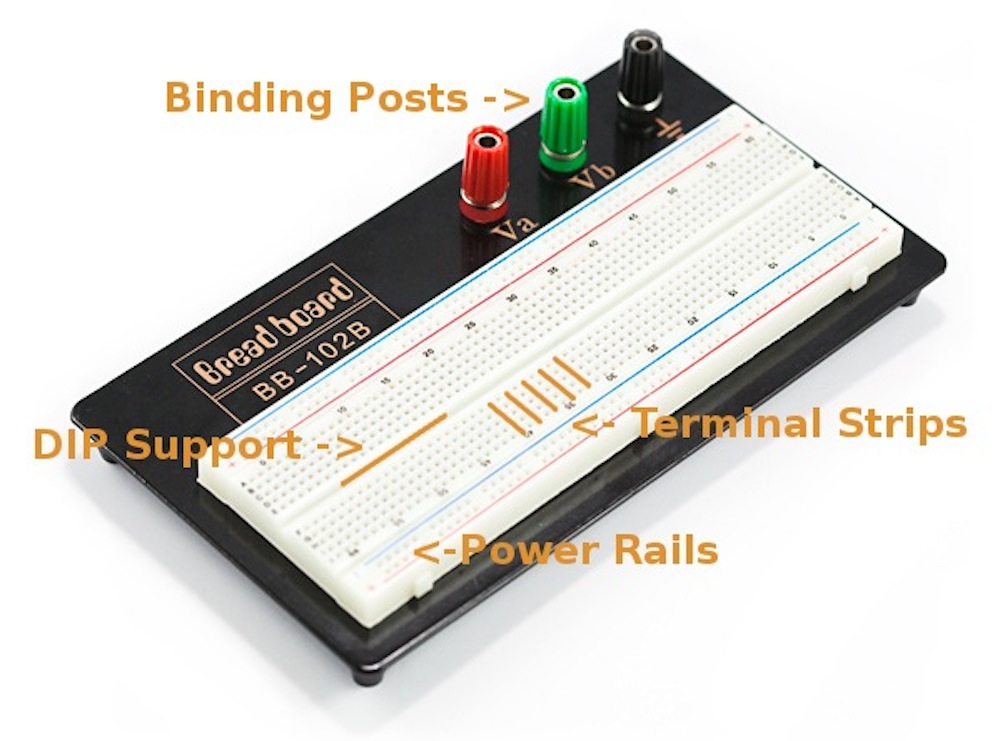
Anatomy:
Power Rails- Give you access to power wherever you need it in your circuit. Labeled either "+" or "-" and have red, black, and blue stripes indicating positive and negative sides. Power rails are not connected and if you want the same power on both sides, you need to connect the rails with jumper wires.
Terminal Strips- Clips allowing for wires or the legs of the components into the exposed holes. Once connected the component will be electrically connected to everything placed in that row. This electrical connection is because the metal rows are conductive allowing current to flow from any point in the strip. Five clips per strip is typical; it means that you can connect up to five components in one section of the breadboard.
DIP Support: The ravine separating the two sides of the breadboard is very important to DIP (Dual in-line Package integrated circuit). The DIP support is useful because each side of a DIP is unique and cannot be connected to each other.
Binding Posts: Allows different kinds of power sources to the breadboard. These posts are not actually connected to the breadboard; need to connect them using jumper wires.
Tuesday, November 13, 2018
What do each of the colors mean?

For the resistor in the circuit that has a first digit brown band (1), second and third digit black band (00), a fourth red band (00), and the fifth band is brown (±1% tolerance). This circuit has 10000 ohms resistance and ±1 % tolerance.
For the resistor that has a first digit brown band (1), second and third digit black band (0), and fourth brown band (±1 % tolerance). This circuit has 10 ohms resistance and ±1% tolerance.
The resistor in the circuit that has five bands brown (1), red (2), brown (or black, unclear because they are burnt) (0), gold, and the thicker band is brown (± 1% tolerance). If the colors are brown, red, black then this resistor has twelve ohm resistance. Because these resistors are connected in parallel the resistance per each resistor is 12/5 ohm.
Another resistor has a brown base and four bands of colors gold (±.5% tolerance), black (0), purple (7 is the second digit), and yellow (4 is the first digit). Has 47 ohm resistance and ±.5 % tolerance.
Friday, November 9, 2018
Electronic Color Code Continued 11/9/18
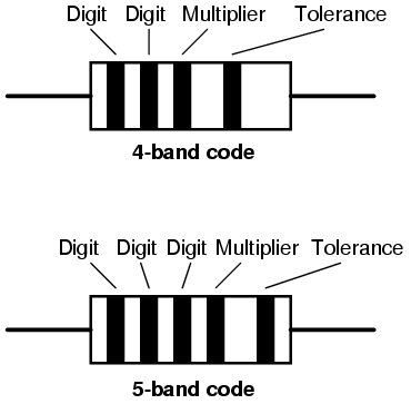
Electronic Color Code: The resistors in the current circuit have 5 or 4 bands of color. The color bands represent the resistors resistance value, tolerance, and wattage rating.
One of the resistors have a thicker brown band farther away from the four other bands. The other 4 other bands are spread out; one band is red, two are black, and the fourth is brown. This resistor also has a blue base color.
The other resistors in the circuit have a thicker brown band followed by a brown band, two black bands, and another brown band. This resistor has a blue base.
Another resistor in the circuit has five bands brown, red, brown (or black, unclear because they are burnt), gold, and the thicker band is brown. If the colors are brown, red, black then this resistor has twelve ohm resistance. Because these resistors are connected in parallel the resistance per each resistor is 12/5 ohm. This resistor has a blue base.
Another resistor has a brown base and four bands of colors gold, black, purple, and yellow.
What do each of the colors mean and how to read them?
zener diode: allows current to flow from its anode to its cathode and in the opposite direction when the zener voltage is reached.
current limiting diode: limits the current to a maximal specified value for the device.
Thursday, November 8, 2018
Exploring the circuit 11/8/18
Integrated Circuits: Are a collection of electric components; resistors, transistors, and capacitors stuffed into a tiny chip. An integrated circuit is comprised of a complex layering of semiconductor wafers, copper, and other materials; these interconnect to form transistors, resistors, and other components.
Integrated circuit dies come in packages which displays it onto a device that is easier to connect to. The outer connections of a die are connected through a gold wire to a pad or pin on the package.
https://learn.sparkfun.com/tutorials/integrated-circuits/all
Electronic Color Code: Used to indicate the values and ratings of electronic components in resistors. The resistors with the existing circuit have five colored bands. The farthest band represents tolerance, the next band represents the multiplier, and the next three bands represent digits.
Wednesday, November 7, 2018
Exploring the Circuit 11/7/18
Transistor: A switch controlled by an electrical circuit.
There are different types of transistors; the most common one is the “bipolar junction transistor” or “BJT”
The BJT has three pins: Base (b), collector (c), and emitter (e)
It comes in two versions: NPN, and PNP
Semiconducting material allows for current to flow from the base to the emitter opening a flow of current from the collector to the emitter. Need to apply voltage to the base to get the current flowing from base to emitter; this turns the transistor ON. Once switching on the transistor current is able to flow from the collector to the emitter. (current will only flow from collector-emitter if transistor is on)
https://www.build-electronic-circuits.com/how-transistors-work/
Transistors can be slightly on and slightly off.
PNP transistor has the same pins as a NPN transistor, however the transistor will turn on when voltage applied to the emitter induces a current flowing from the emitter to the base. Once turned on there is then a large current between the emitter and the collector.
Voltage applied to the base must be 0.7v lower then the emitter in order for current to flow from emitter to base. Since voltage on base must be lower then emitter, emitter should be connected to the plus of the power source.
https://www.build-electronic-circuits.com/pnp-transistor/
Monday, November 5, 2018
Exploring the circuit 11/5/18
thinner the film the less voltage needed
our film is thicker, requires very high voltage
Goal of original circuit was to get voltage from audio signal
current limiting dial; in case of leak minimize shock despite high voltage
bread board used for prototyping; I need to learn how to use a bread board.
https://learn.sparkfun.com/tutorials/how-to-use-a-breadboard/all
resistor
bleeder resistor: a resistor connected in parallel with the output of a high voltage power supply circuit.
https://en.wikipedia.org/wiki/Bleeder_resistor
capacitor
stores potential energy in an electrical field
analog; result is not 1 and 0 it is something in between
Need to learn about analog circuit design
I need to reverse engineer the circuit trying to figure out the purpose of the connections made.
Friday, November 2, 2018
Exploring Senseg/ Prior circuits
The Senseg Feelscreen Developer Kit is helpful in visualizing the goal of my project. It also shows the Electrovibration phenomenon. The Senseg is limiting because it is one pixel and uses visual guidance and position of the finger to trick the user into thinking there is haptic feedback in only one part of the screen. In reality when you touch part of the screen, turning on the haptic feedback, the electrovibration sensation can be felt on the whole screen not just the specific area.
After exploring the Senseg it's clear that I have to create a new screen and circuit that enables multiple pixels. With multiple pixels the electrovibration sensation will be felt on specific areas of the screen only, allowing someone who can't see to feel specific effects without relying on vision to differentiate the part of the screen with the perceived haptic feedback.
Looking at the circuit and screen already built I have to spend some time exploring them and my next step would be building off of what is made.
The screen already built appears to be made of copper board and an insulating film. Goal is for copper board to be a grid and connecting certain number of points (multiple pixels) can feel a shape.
Subscribe to:
Posts (Atom)
-
https://www.analog.com/en/education/education-library/tutorials/analog-electronics.html https://www.youtube.com/watch?v=F3iJUTa-Hi8 Used...
-
Integrated Circuits: Are a collection of electric components; resistors, transistors, and capacitors stuffed into a tiny chip. An integrated...
-
Transistor: A switch controlled by an electrical circuit. There are different types of transistors; the most common one is the “bipolar ju...
